Project 1: Not-Paper Airplane
For the midterm project, I decided to design and print an airplane-like fixed-wing aircraft that was capable of gliding after being hand-launched (or, put less technically, thrown).
Background
I have had personal relationship with flying for many years. I am a pilot, and I started flying at age 14. At 15, I became interested in aerobatics and began my journey into competitive aerobatic flying.
 For the third homework of the class, I designed and 3D printed a model of a fighter jet (pictured). This jet, while having an aesthetically pleasing design, is very unlikely to ever fly. The wings are simply sheared trapezoids, and the overall design is better suited for supersonic flight, rather than a leisurely throw indoors.
However, I believed it was possible to 3D print an airplane that could fly similarly to a paper airplane, despite the relatively large weight that a PLA model has when compared to a sheet of paper.
Design Overview And Problems
Even before the prototyping phase of design, several problems were obvious:
As previously stated, PLA is quite heavy when compared to paper, and the larger the model, the more the total weight will increase. However, from previous experience with 3D printing, I knew that designs with very low infill could be unexpectedly strong while remaining lightweight. Since the exterior of the airplane must be solid, there must exist an ideal ratio of model size to lift that would provide the best glide performance.
In its typical usage scenario, the airplane would be gliding at a very low airspeed. This implied that the wings would need to have a large area compared to non-lift producing surfaces, such as the body.
A freehand throw is not very precise. The airplane would need to have a properly-designed tailplane to resist departure from controlled flight. If the body were to rotate out of the relative wind, a properly designed tail would provide an opposite force to right the airplane. However, a tail designed without this in mind could further "enhance" any tendency to depart controlled flight and tumble
Smooth surfaces are important for fixed-wing aircraft, so much so that many pilots report appreciable cruise speed increases after having their airplane painted. Since the portion of models that printed on the bed or support material tend to have a rough finish, this was a major concern.
Preexisting Research
Before beginning my own work, I researched this topic to determine if similar projects already existed. While I found several people who had designed RC airplanes, I did not find many, if any, paper airplane-esque designs.
Regarding the RC airplanes, some used the frame-and-fabric design, while others used an entirely 3D printed design. See the next section for a description of these terms.
Initial Design
 Initially, the design goal was to model and 3D print a series of longerons and spars to make a frame of an airplane, in much the same way that wood is used to make a frame for many fabric-based airplanes. I planned to cover this frame with a cloth, such as dacron, and apply a dope to constrict and smooth the fabric. However, I decided that I did not have enough time to design such an intricate system, so I elected to design and print the airplane as one solid piece.
Prototype 1
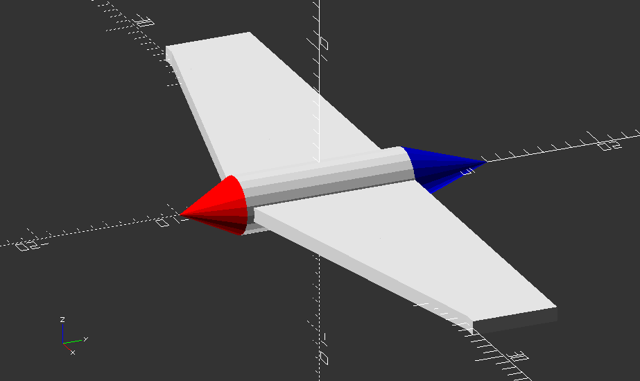 The first designs of the airplane began with a parametrically-designed body, nose, and tail. The nose came to a perfect point to promote aerodynamics. The wings at this stage were simply sheared trapezoids, much like the fighter jet.
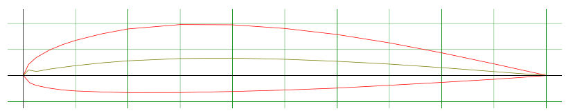
 After some failed attempts to design a proper wing, I decided that true aeronautical engineers could design a wing better than a Computer Science student. I procured the design for a Boeing 106 airfoil and used OpenSCAD's linear extrusion function to generate a 3D model of the wing. To further the sleek design of the airplane, I also tapered the wings using an external library.
Using reference photos of light aircraft and discussions on RC airplane forums, I estimated a size for the tailplane (that is, the horizontal and vertical stabilizers). According to these estimates, the absolute size for these components appeared too small to be effective. However, there are very few negative effects to having an enlarged tailplane, so the tailplane was scaled up to about 1/3 the width of the main wings.
After some failed attempts to design a proper wing, I decided that true aeronautical engineers could design a wing better than a Computer Science student. I procured the design for a Boeing 106 airfoil and used OpenSCAD's linear extrusion function to generate a 3D model of the wing. To further the sleek design of the airplane, I also tapered the wings using an external library.
Using reference photos of light aircraft and discussions on RC airplane forums, I estimated a size for the tailplane (that is, the horizontal and vertical stabilizers). According to these estimates, the absolute size for these components appeared too small to be effective. However, there are very few negative effects to having an enlarged tailplane, so the tailplane was scaled up to about 1/3 the width of the main wings.
Prototype 2
Somewhat to my surprise, Prototype 1 did fly. However, it needed quite a high speed to glide successfully. I hypothesized that this problem could be improved by:
"Clipping" the wings, as rectangular wings would not lose area to the taper
Extending the wings
 After printing, this design did not look as appealing as Prototype 1. Additionally, its flight performance was worse than Prototype 1. The reason for this was rather straightforward: although the wings' length was extended, the width was not. This resulted in too much of the wing being the solid exterior layer, and adding too much weight without adding significant additional lift.
Prototype 3
 After the lackluster performance of Prototype 2, I considered what changes in the airplane's design may affect its low-speed performance. The largest factor that contributed to the lack of glide performance was most likely the small size of the wings.
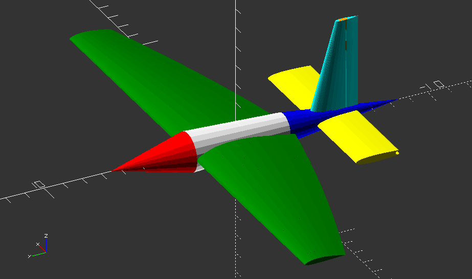
Therefore, Prototype 3 used an unconventionally-modified delta wing design. Most delta wing designs in full-scale airplanes improve extremely high-speed flight characteristics, but the cross section of this design is a standard airfoil (the Boeing 106), expanded to use the previously-unused area near the top of the body.
The addition of the winglets was partly stylistic and partly functional. In full-scale aircraft, winglets improve the flight characteristics of airplanes in low-speed flight, but the advantages at such a small scale are likely negligible. While this design did glide, printing was a major issue (see below), and performance was not greatly improved from Prototype 1.
After the lackluster performance of Prototype 2, I considered what changes in the airplane's design may affect its low-speed performance. The largest factor that contributed to the lack of glide performance was most likely the small size of the wings.
Therefore, Prototype 3 used an unconventionally-modified delta wing design. Most delta wing designs in full-scale airplanes improve extremely high-speed flight characteristics, but the cross section of this design is a standard airfoil (the Boeing 106), expanded to use the previously-unused area near the top of the body.
The addition of the winglets was partly stylistic and partly functional. In full-scale aircraft, winglets improve the flight characteristics of airplanes in low-speed flight, but the advantages at such a small scale are likely negligible. While this design did glide, printing was a major issue (see below), and performance was not greatly improved from Prototype 1.
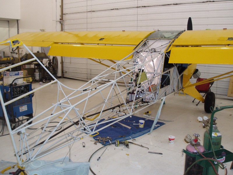
Print Experiences And Issues
Prototypes 1 and 2 printed with very little issue. They were both printed using 10% infill in a honeycomb pattern, and their support material was removable from the model with little issue.
Prototype 3 was extremely difficult to print. Since the bottom of the body was not attached to the wings itself, the body was only in contact with the bed on a very small sliver. The severe curling that resulted caused the head of the printer to collide with the body and knock it entirely off the bed.
When Prototype 3 was printed on another model of printer, the print completed, but it was very flimsy. This was to the point where I considered the print too unstable to remove from the support material.
Eventually, I decided to print Prototype 3 upside down. While this made for an obscene amount of support material, the print did complete successfully with very little curling.
Print Gallery
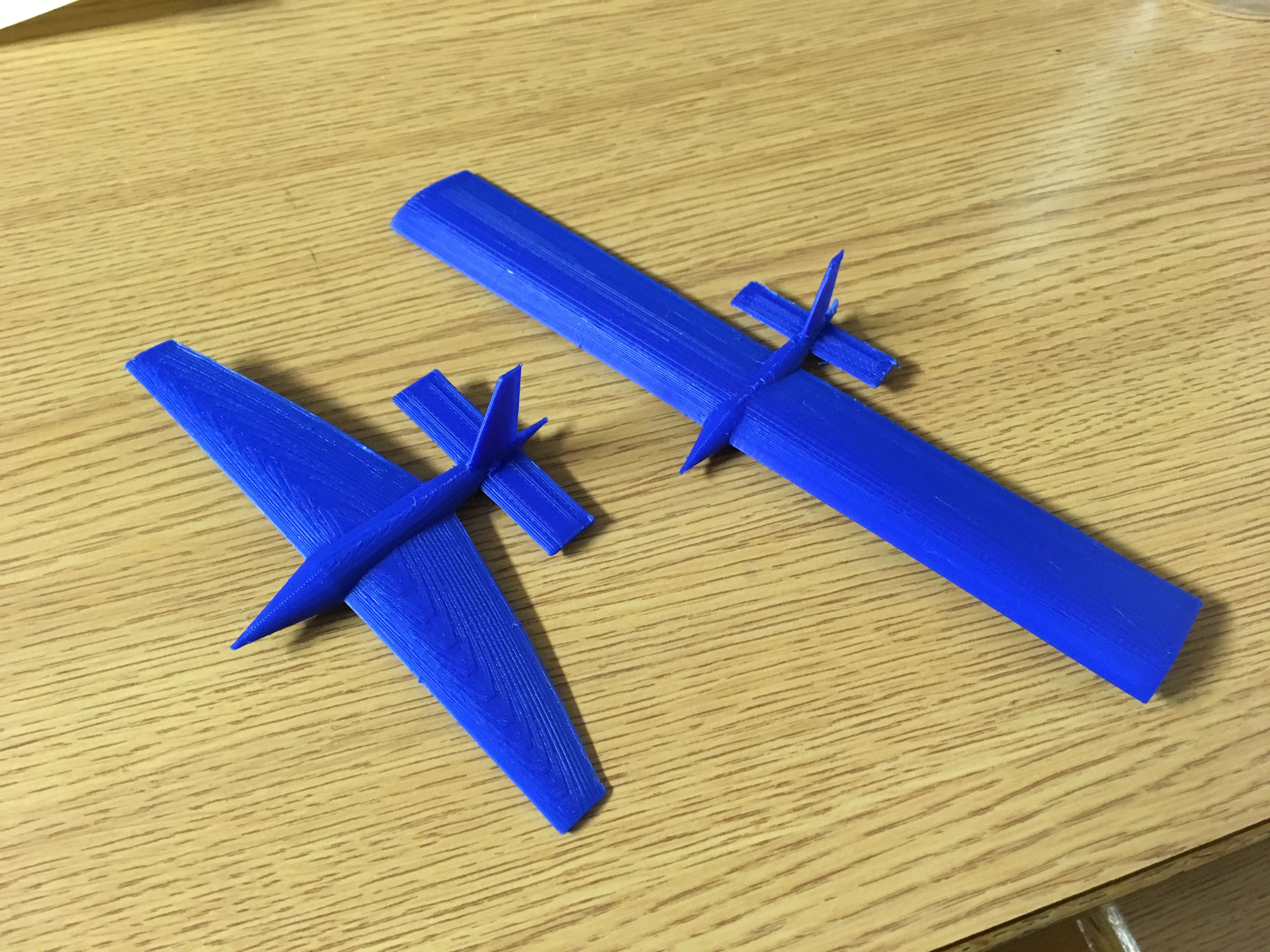
The first two prints. Prototype 1 is below, and Prototype 1 above.
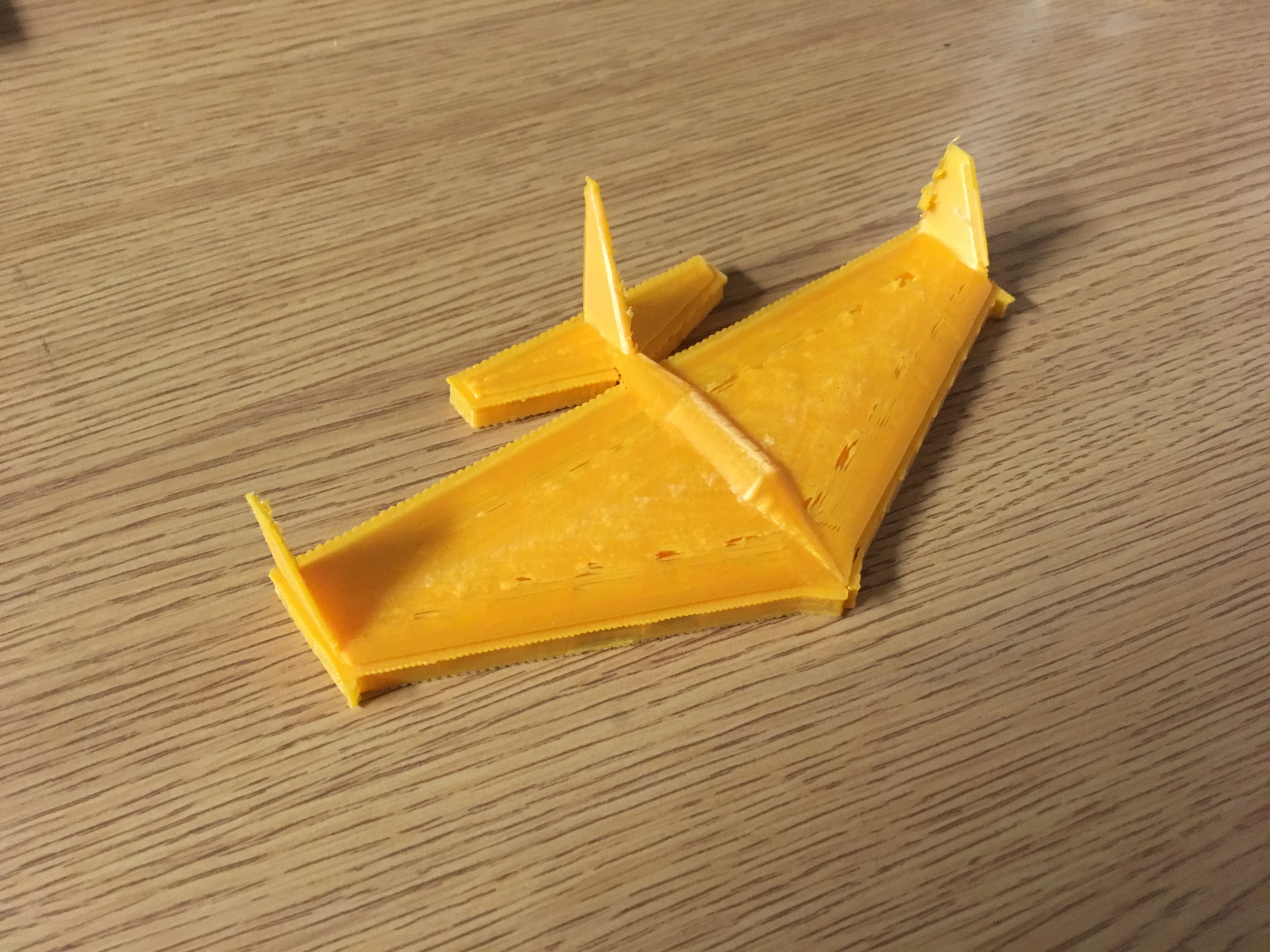
The first print of Prototype 3 that completed without the print head prematurely ripping the print off the bed. In actuality, the print head did rip half of the body off of this print, but it managed to print the second half of the bod. The lack of body, and therefore poor body-wing connection, made the print too fragile to remove from the support material.
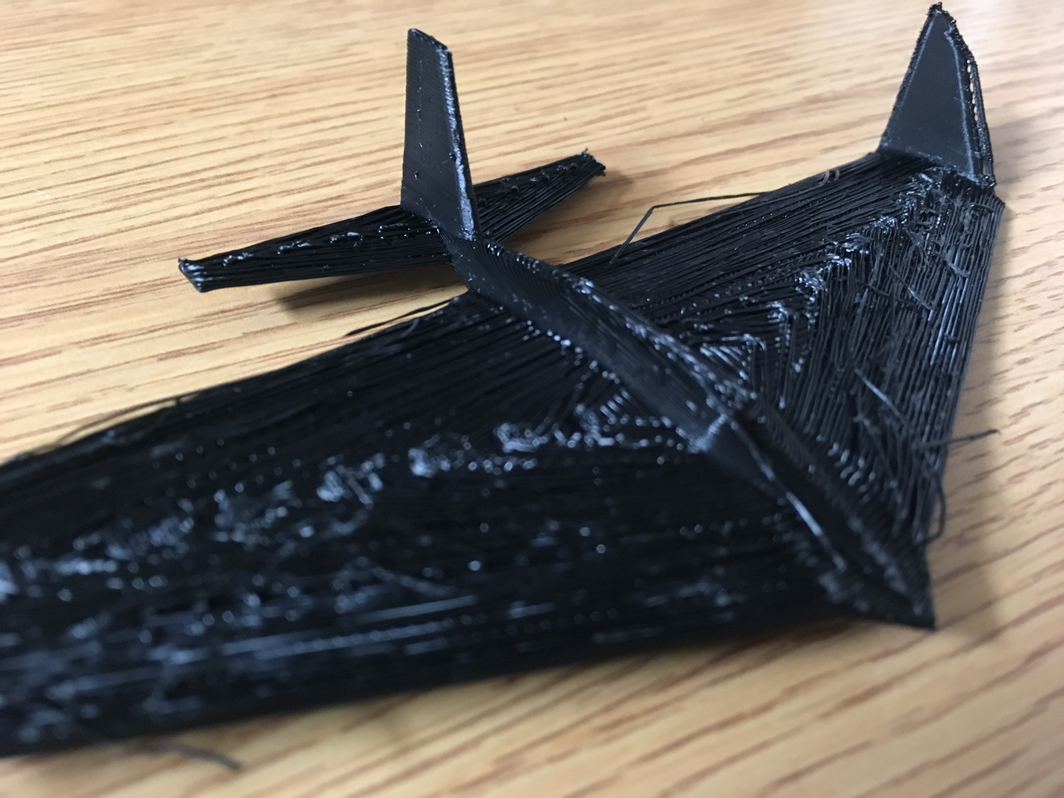
The version of the Delta Wing prototype that printed upside-down. This helped stability during the print dramatically.
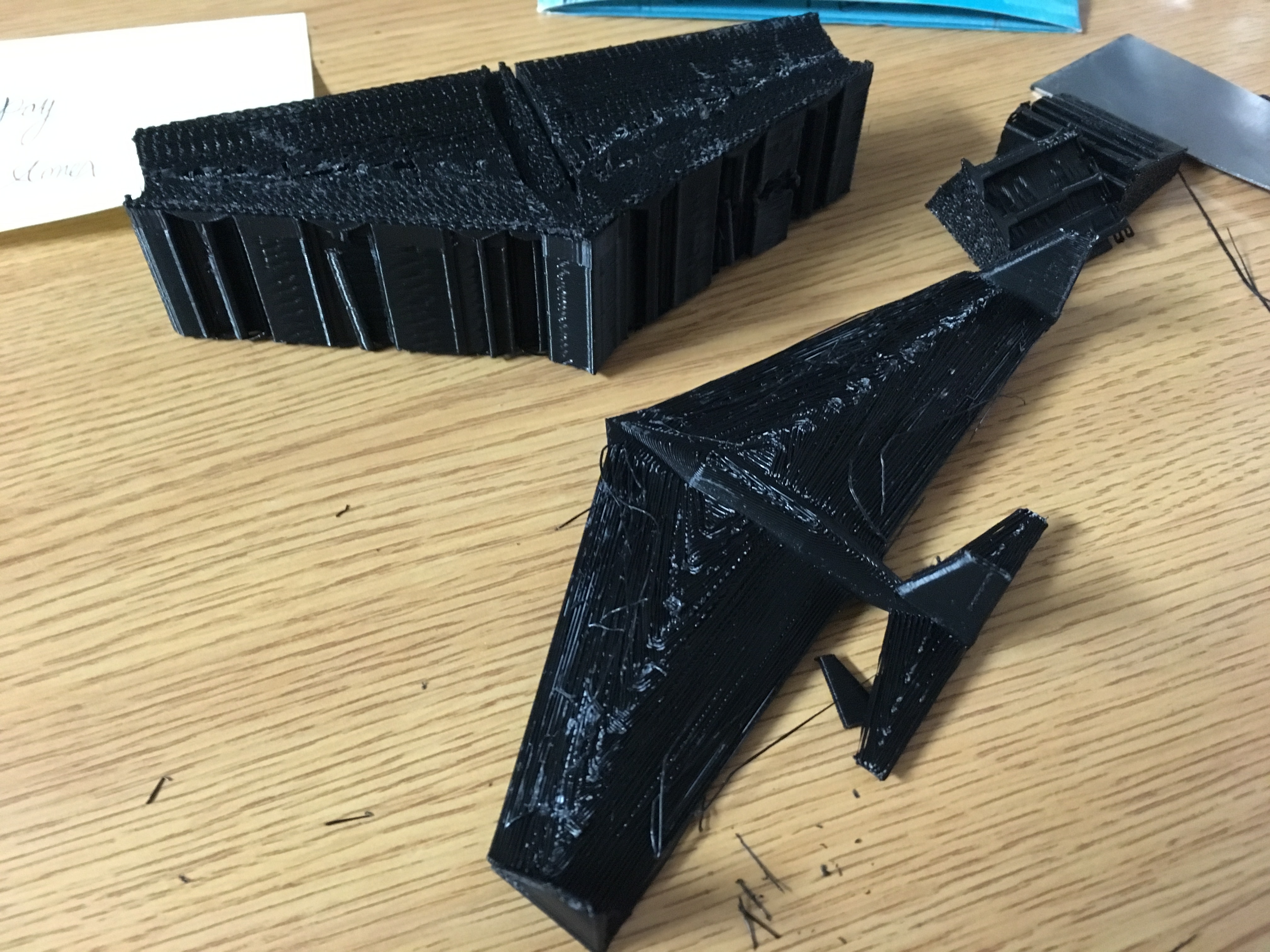
The massive amount of support material that was required to print the Delta Wing, next to the airplane itself for scale.
Future Development
For further research/development into this project, I would try to print a version of Prototype 1 on a larger scale, as this would provide more wing area with less wing-mass (i.e more of the model is light infill).
I would also like to produce a version of Prototype 1 with an elongated body, so that the wings could be wider. In full-scale airplane design, the only common way to increase an airplane's wingspan is to lengthen the wings, so I carried this over into the design of Prototype 2. However, since OpenSCAD knows no such limitations, this would likely improve the flight characteristics of the airplane.
- Collin's Other Sites
- -----
- clasley Home
- Ice Skating